Lab 3 - Creating Custom IP Blocks
In this tutorial, we show how to create a custom IP block that houses two DDS modules capable of producing simultaneous samples at each clock cycle to create a tone. The tone is tunable via writing to the register space with applications run on the processor system (i.e., Linux or baremetal commands).
Creation Wizard
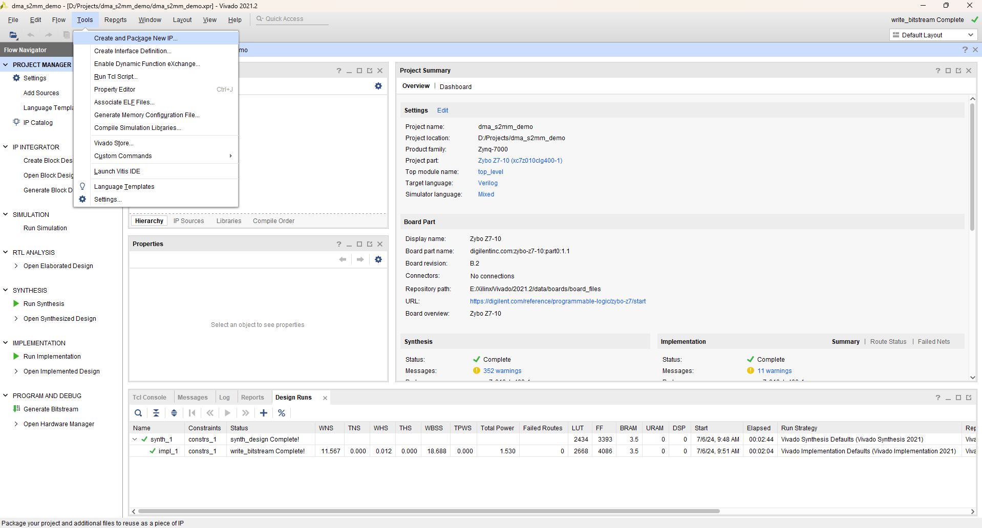
Open up a new or existing project with Vivado, doesn’t matter which. What you want is to click Tools and then find and click Create and Package New IP…
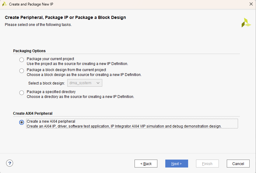
A wizard will pop up, select Create a new AXI4 peripheral. Click Next.
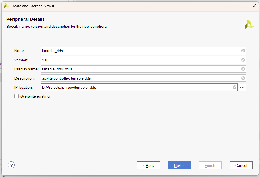
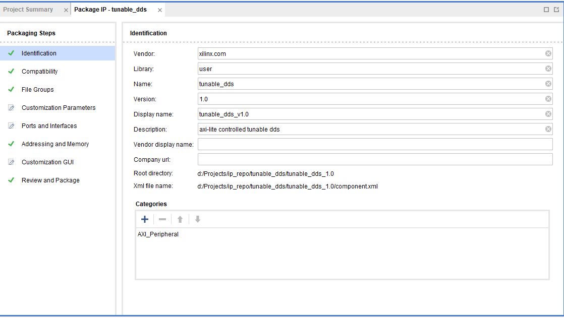
Name and describe the IP block as shown in the below figure
Note
Highly recommend creating a folder within your IP repository as shown in the figure below with ip_repo/tunable_dds, this allows you to store all project files associated with the custom IP block in one directory.
Click Next.
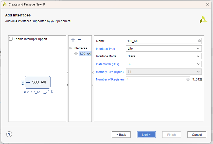
Keep all default settings. Click Next.
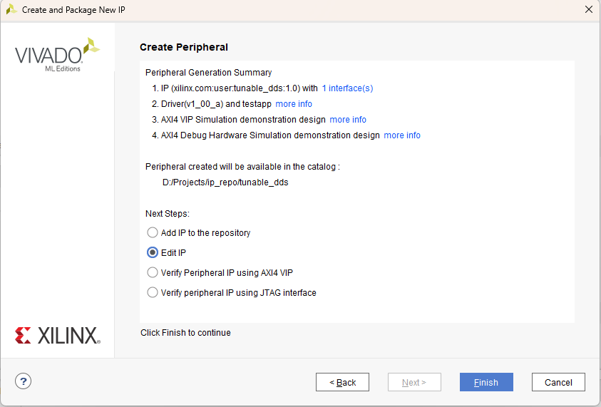
Ensure that Edit IP is selected, or you’ll have to redo all these previous steps…
Click Finish.
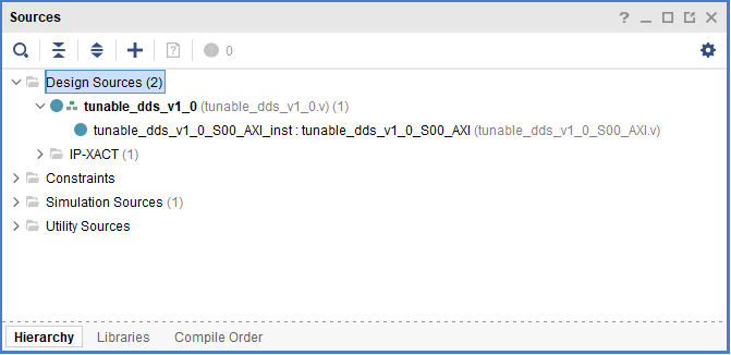
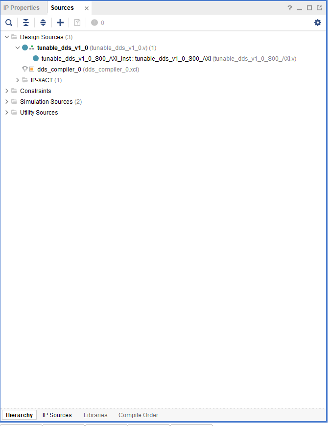
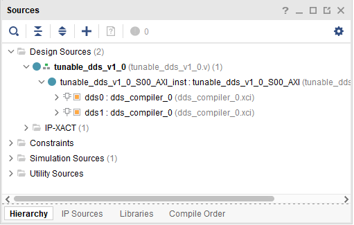
Your project sources will look like the following,
Add IP to Custom IP
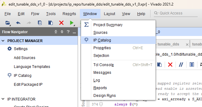
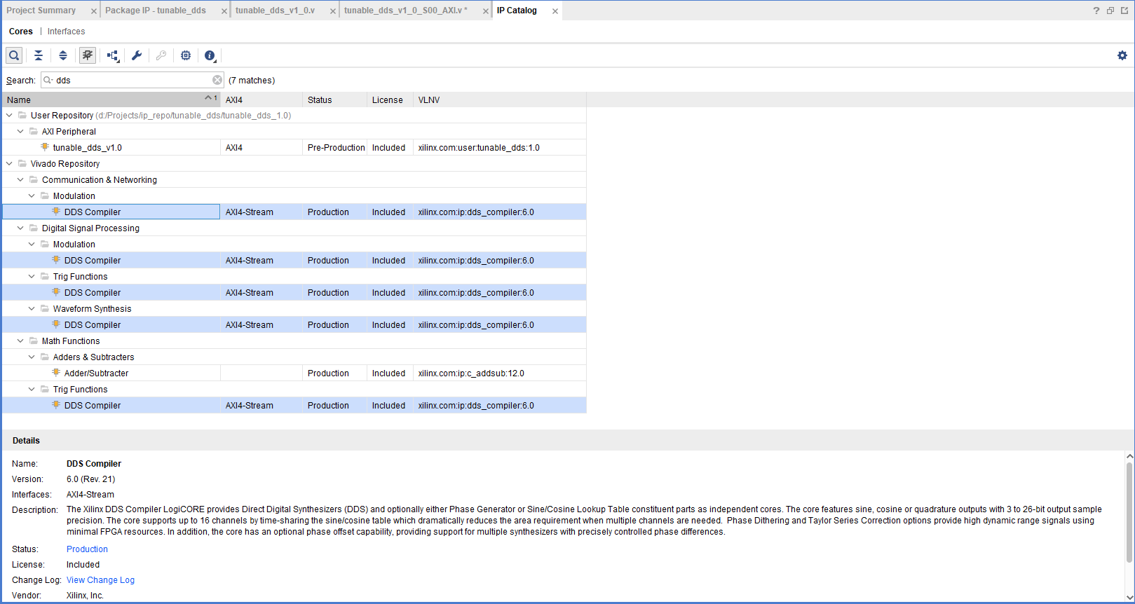
Click Window and open the IP Catalog.
Search dds and double-click DDS Compiler, any of the options will work.
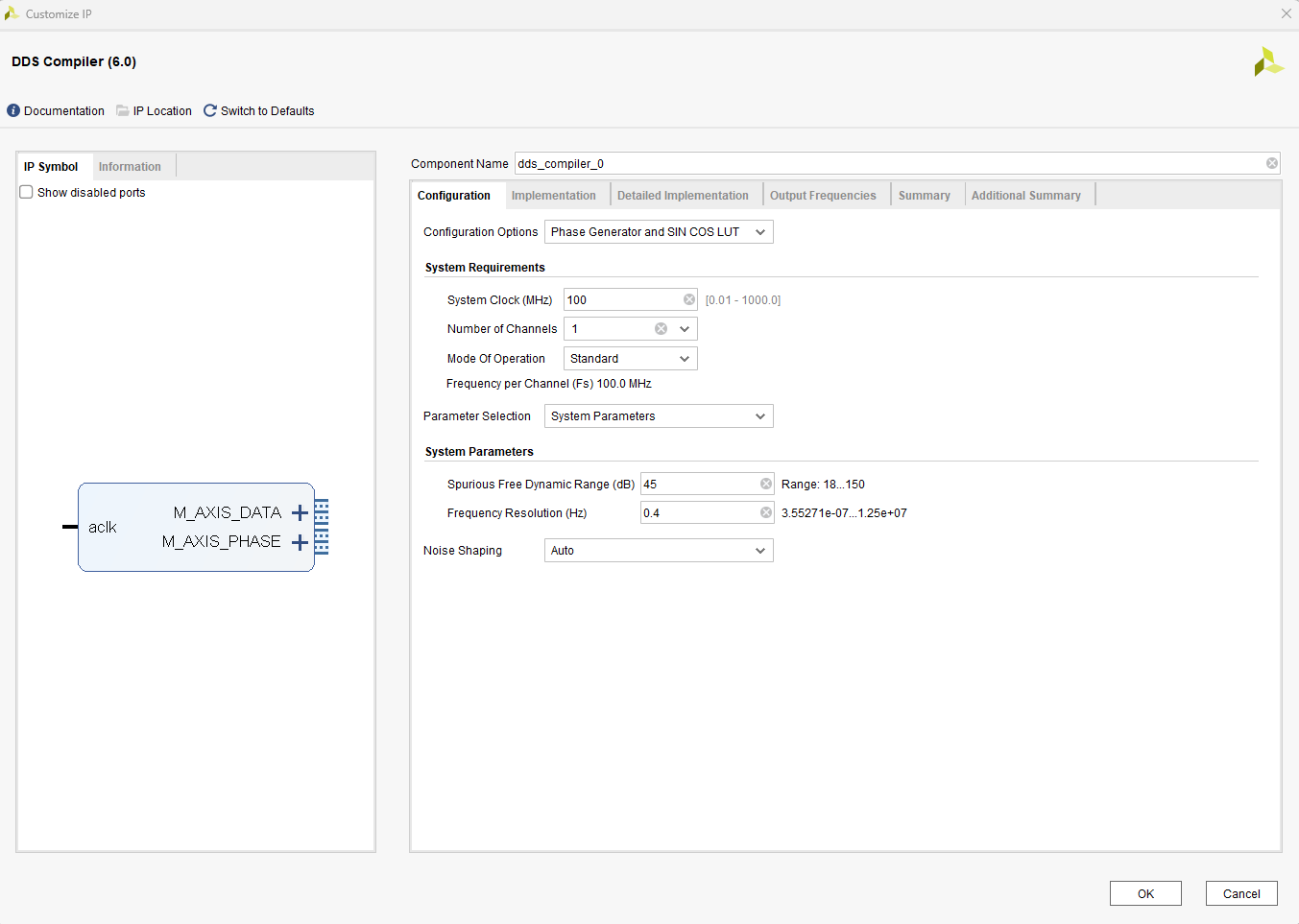
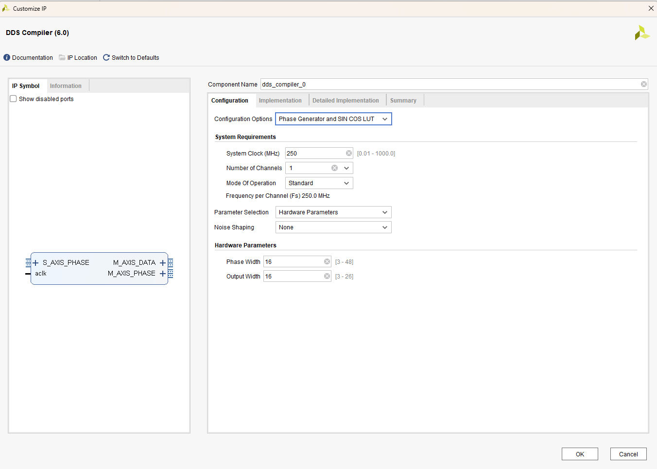
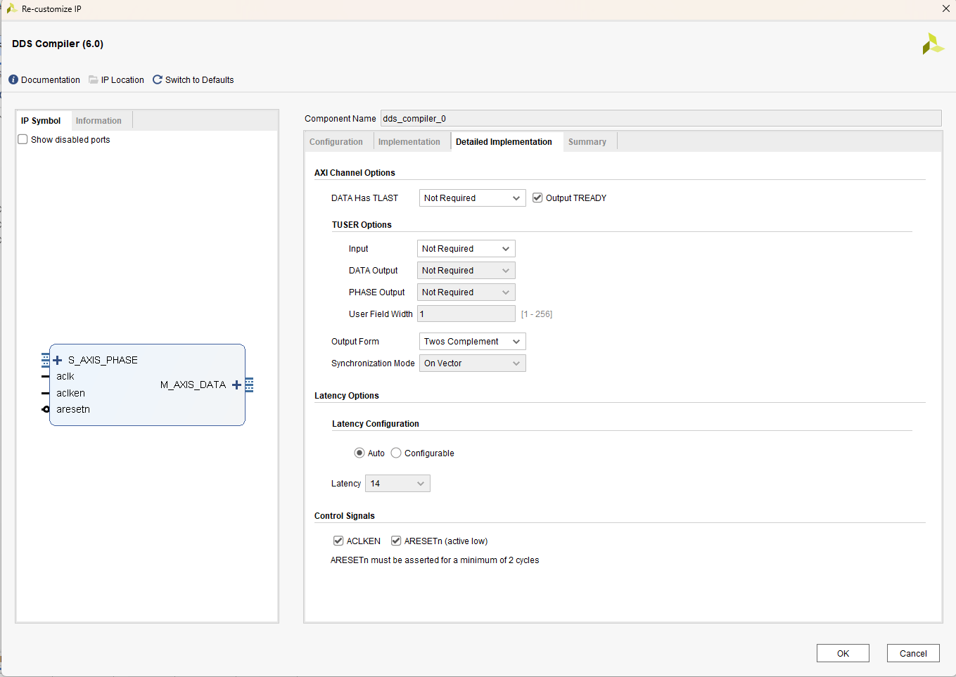
The Customize IP wizard will launch, adjust to the following settings for each screen. Click Ok when finished.
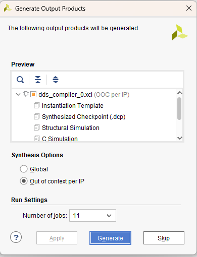
Press Skip
Find and click IP Sources located along the bottom of the Sources tab.
Expand the menu, double-click dds_compiler_0.veo to open it.
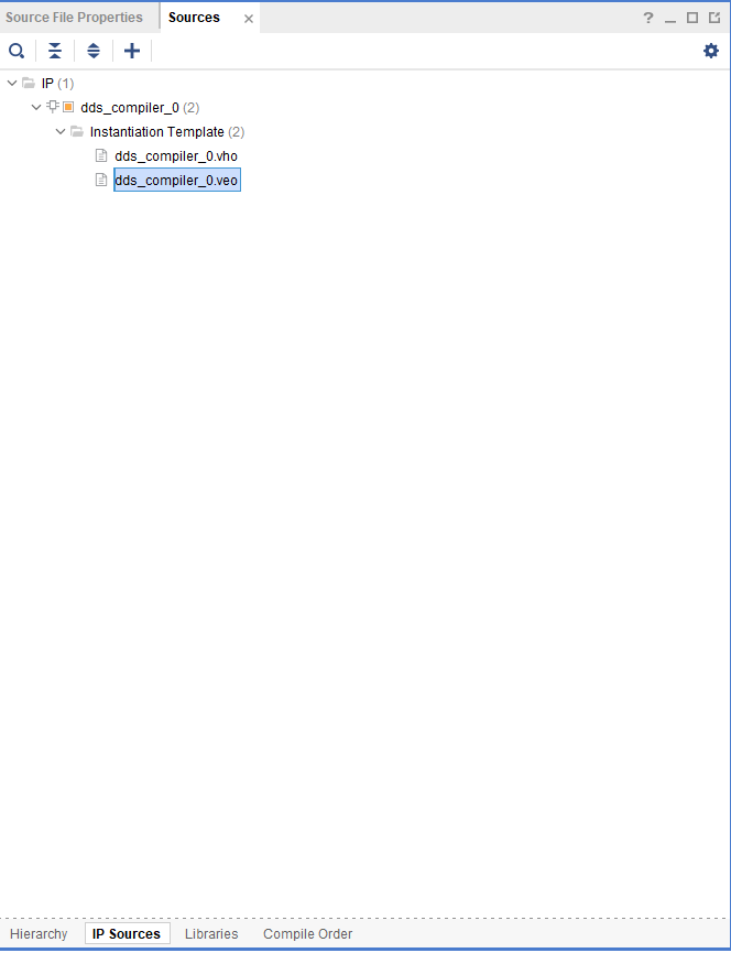
Inside you will find an instantiation template shown below for the DDS Compiler block. This is a handy tool for use of many AMD/Xilinx IP. Keep this file open in your project dashboard, we will revisit it shortly.
//....
//----------- Begin Cut here for INSTANTIATION Template ---// INST_TAG
dds_compiler_0 your_instance_name (
  .aclk(aclk),                                // input wire aclk
  .aclken(aclken),                            // input wire aclken
  .aresetn(aresetn),                          // input wire aresetn
  .s_axis_phase_tvalid(s_axis_phase_tvalid),  // input wire s_axis_phase_tvalid
  .s_axis_phase_tready(s_axis_phase_tready),  // output wire s_axis_phase_tready
  .s_axis_phase_tdata(s_axis_phase_tdata),    // input wire [31 : 0] s_axis_phase_tdata
  .m_axis_data_tvalid(m_axis_data_tvalid),    // output wire m_axis_data_tvalid
  .m_axis_data_tready(m_axis_data_tready),    // input wire m_axis_data_tready
  .m_axis_data_tdata(m_axis_data_tdata)      // output wire [31 : 0] m_axis_data_tdata
);
// INST_TAG_END ------ End INSTANTIATION Template ---------
//....
Adding User Ports and Logic
Within tunable_dds_v1_0.v, find the lines of code toward the top,
// Users to add ports here

// User ports ends
// Users to add ports here

output wire [63:0] M_AXIS_DATA_tdata,
output wire M_AXIS_DATA_tvalid,
input wire M_AXIS_DATA_tready,
input wire M_AXIS_CLK,

// User ports ends
Then, scroll down within tunable_dds_v1_0.v, and find the instantiation template
// Instantiation of Axi Bus Interface S00_AXI
    tunable_dds_v1_0_S00_AXI # (
        .C_S_AXI_DATA_WIDTH(C_S00_AXI_DATA_WIDTH),
        .C_S_AXI_ADDR_WIDTH(C_S00_AXI_ADDR_WIDTH)
    ) tunable_dds_v1_0_S00_AXI_inst (
        .S_AXI_ACLK(s00_axi_aclk),
        .S_AXI_ARESETN(s00_axi_aresetn),
        .S_AXI_AWADDR(s00_axi_awaddr),
        .S_AXI_AWPROT(s00_axi_awprot),
        .S_AXI_AWVALID(s00_axi_awvalid),
        .S_AXI_AWREADY(s00_axi_awready),
        .S_AXI_WDATA(s00_axi_wdata),
        .S_AXI_WSTRB(s00_axi_wstrb),
        .S_AXI_WVALID(s00_axi_wvalid),
        .S_AXI_WREADY(s00_axi_wready),
        .S_AXI_BRESP(s00_axi_bresp),
        .S_AXI_BVALID(s00_axi_bvalid),
        .S_AXI_BREADY(s00_axi_bready),
        .S_AXI_ARADDR(s00_axi_araddr),
        .S_AXI_ARPROT(s00_axi_arprot),
        .S_AXI_ARVALID(s00_axi_arvalid),
        .S_AXI_ARREADY(s00_axi_arready),
        .S_AXI_RDATA(s00_axi_rdata),
        .S_AXI_RRESP(s00_axi_rresp),
        .S_AXI_RVALID(s00_axi_rvalid),
        .S_AXI_RREADY(s00_axi_rready)
    );
Append entries at the bottom as
// Instantiation of Axi Bus Interface S00_AXI
    tunable_dds_v1_0_S00_AXI # (
        .C_S_AXI_DATA_WIDTH(C_S00_AXI_DATA_WIDTH),
        .C_S_AXI_ADDR_WIDTH(C_S00_AXI_ADDR_WIDTH)
    ) tunable_dds_v1_0_S00_AXI_inst (
        .S_AXI_ACLK(s00_axi_aclk),
        .S_AXI_ARESETN(s00_axi_aresetn),
        .S_AXI_AWADDR(s00_axi_awaddr),
        .S_AXI_AWPROT(s00_axi_awprot),
        .S_AXI_AWVALID(s00_axi_awvalid),
        .S_AXI_AWREADY(s00_axi_awready),
        .S_AXI_WDATA(s00_axi_wdata),
        .S_AXI_WSTRB(s00_axi_wstrb),
        .S_AXI_WVALID(s00_axi_wvalid),
        .S_AXI_WREADY(s00_axi_wready),
        .S_AXI_BRESP(s00_axi_bresp),
        .S_AXI_BVALID(s00_axi_bvalid),
        .S_AXI_BREADY(s00_axi_bready),
        .S_AXI_ARADDR(s00_axi_araddr),
        .S_AXI_ARPROT(s00_axi_arprot),
        .S_AXI_ARVALID(s00_axi_arvalid),
        .S_AXI_ARREADY(s00_axi_arready),
        .S_AXI_RDATA(s00_axi_rdata),
        .S_AXI_RRESP(s00_axi_rresp),
        .S_AXI_RVALID(s00_axi_rvalid),
        .S_AXI_RREADY(s00_axi_rready),
        .M_AXIS_DATA_tdata(M_AXIS_DATA_tdata),
        .M_AXIS_DATA_tvalid(M_AXIS_DATA_tvalid),
        .M_AXIS_DATA_tready(M_AXIS_DATA_tready),
        .M_AXIS_CLK(M_AXIS_CLK)
    );
You can go ahead and close tunable_dds_v1.v, we’re done with that one. The next steps will look familiar, make sure you’re editing the correct file.
Within the tunable_dds_v1_0_S00_AXI.v file, find the comments toward the top
// Users to add ports here

// User ports ends
Edit the code to read as
// Users to add ports here

output wire [63:0] M_AXIS_DATA_tdata,
output wire M_AXIS_DATA_tvalid,
input wire M_AXIS_DATA_tready,
input wire M_AXIS_CLK,

// User ports ends
Find the lines at the bottom of tunable_dds_v1_0_S00_AXI.v
// Add user logic here

// User logic ends
Our implementation requires creating two samples simultaneously, in order to realize this, two DDS are required. Copy paste the instantiation template (from dds_compiler_0.veo that you openned earlier) twice, rename from your_instance_name to dds0 and dds1.
// Add user logic here
dds_compiler_0 dds0 (
  .aclk(aclk),                                // input wire aclk
  .aclken(aclken),                            // input wire aclken
  .aresetn(aresetn),                          // input wire aresetn
  .s_axis_phase_tvalid(s_axis_phase_tvalid),  // input wire s_axis_phase_tvalid
  .s_axis_phase_tdata(s_axis_phase_tdata),    // input wire [31 : 0] s_axis_phase_tdata
  .m_axis_data_tvalid(m_axis_data_tvalid),    // output wire m_axis_data_tvalid
  .m_axis_data_tdata(m_axis_data_tdata)      // output wire [31 : 0] m_axis_data_tdata
);

dds_compiler_0 dds1 (
  .aclk(aclk),                                // input wire aclk
  .aclken(aclken),                            // input wire aclken
  .aresetn(aresetn),                          // input wire aresetn
  .s_axis_phase_tvalid(s_axis_phase_tvalid),  // input wire s_axis_phase_tvalid
  .s_axis_phase_tdata(s_axis_phase_tdata),    // input wire [31 : 0] s_axis_phase_tdata
  .m_axis_data_tvalid(m_axis_data_tvalid),    // output wire m_axis_data_tvalid
  .m_axis_data_tdata(m_axis_data_tdata)      // output wire [31 : 0] m_axis_data_tdata
);
// User logic ends
Now comes the key part, we need to tie the slv_reg variables to those s_axis_phase_ inputs for the instantiation. Ultimately, the slv_reg variables will reference a piece of memory that we will write to with our embedded system. The addresses are auto-assigned whenever this block is used in a Vivado design, i.e., a base register of 0xa0000000 corresponds to slv_reg0 and since our register address width (C_S_AXI_ADDR_WIDTH) is 4, slv_reg1 corresponds to 0xa0000004.
Add/change to the code as follows:
At the bottom of the code snippet,
assign dds_resetn = steady_slv_reg0[0];, andassign phz_inc_start = slv_reg1[15:0];map the register space to values that feed our DDS.Note the change of using
M_AXIS_CLKfor the.aclkandM_AXIS_DATA_tready.The handshaking
M_AXIS_DATA_tvalidis a logical AND combination from both DDS.We lead the phase of
dds1by and offset of half the phase increment rate, this is accomplished by a barrel shiftphz_inc_start >> 1. This creates a set of two time samples at each clock cycle.
// Add user logic here

wire dds_resetn;

wire [15:0] phz_inc_start;

reg [31:0] m0_axis_data_tdata;
reg m0_axis_data_tvalid;

reg [31:0] m1_axis_data_tdata;
reg m1_axis_data_tvalid;

dds_compiler_0 dds0 (
  .aclk(M_AXIS_CLK),                                // input wire aclk
  .aclken(1),                                       // input wire aclken
  .aresetn(dds_resetn),                             // input wire aresetn
  .s_axis_phase_tvalid(1),                          // input wire s_axis_phase_tvalid
  .s_axis_phase_tdata({16'b0,phz_inc_start}),       // input wire [31 : 0] s_axis_phase_tdata
  .m_axis_data_tvalid(m0_axis_data_tvalid),         // output wire m_axis_data_tvalid
  .m_axis_data_tready(M_AXIS_DATA_tready),          // input wire m_axis_data_tready
  .m_axis_data_tdata(m0_axis_data_tdata)            // output wire [31 : 0] m_axis_data_tdata
);

dds_compiler_0 dds1 (
  .aclk(M_AXIS_CLK),                                            // input wire aclk
  .aclken(1),                                                   // input wire aclken
  .aresetn(dds_resetn),                                         // input wire aresetn
  .s_axis_phase_tvalid(1),                                      // input wire s_axis_phase_tvalid
  .s_axis_phase_tdata({phz_inc_start >> 1, phz_inc_start}),     // input wire [31 : 0] s_axis_phase_tdata
  .m_axis_data_tvalid(m1_axis_data_tvalid),                     // output wire m_axis_data_tvalid
  .m_axis_data_tready(M_AXIS_DATA_tready),                      // input wire m_axis_data_tready
  .m_axis_data_tdata(m1_axis_data_tdata)                        // output wire [31 : 0] m_axis_data_tdata
);

assign M_AXIS_DATA_tdata = {m1_axis_data_tdata,m0_axis_data_tdata};
assign M_AXIS_DATA_tvalid = m0_axis_data_tvalid & m1_axis_data_tvalid;

assign dds_resetn = steady_slv_reg0[0];
assign phz_inc_start = slv_reg1[15:0];

// User logic ends
Your project sources should now look like the following,
Packaging the Custom IP
Along the Flow Navigator side bar, click Edit Packaged IP.
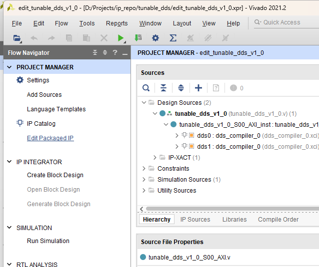
This opens the tab shown below.
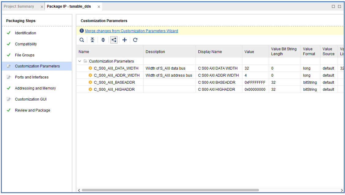
Click on Customization Parameters, and then click Merge changes from Customization Parameters Wizard, press Ok through any prompts.
Click on Ports and Interfaces, this next bit is important to ensure the peripheral has a correct AXI-Stream interface.
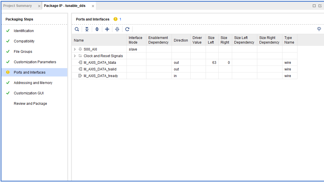
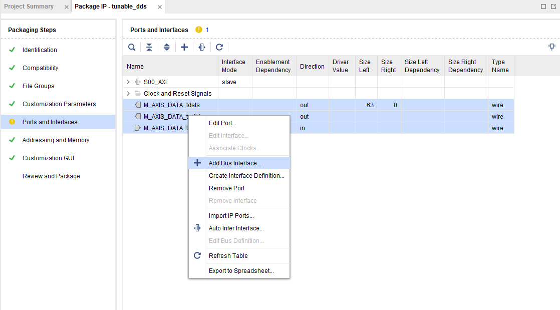
Select the group of ports by Ctrl + click each one, then Right click on a member of the group to open the menu, click + Add Bus Interface…
Click the elipsis … on the side.
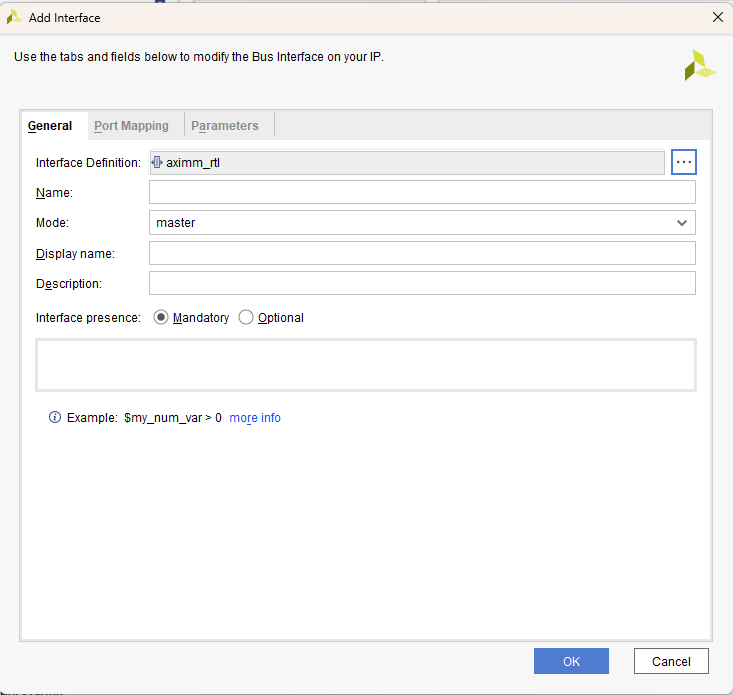
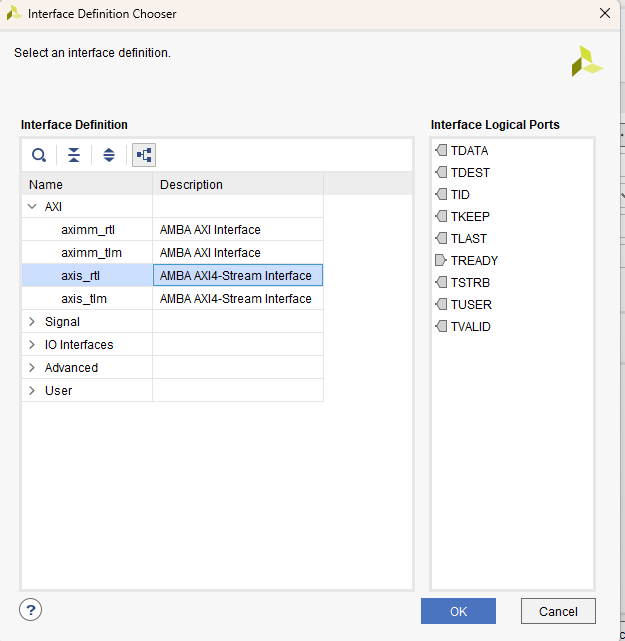
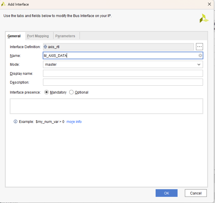
Select axis_rtl corresponding to AMBA AXI4-Stream Interface. Click Ok
Change the name to M_AXIS_DATA.
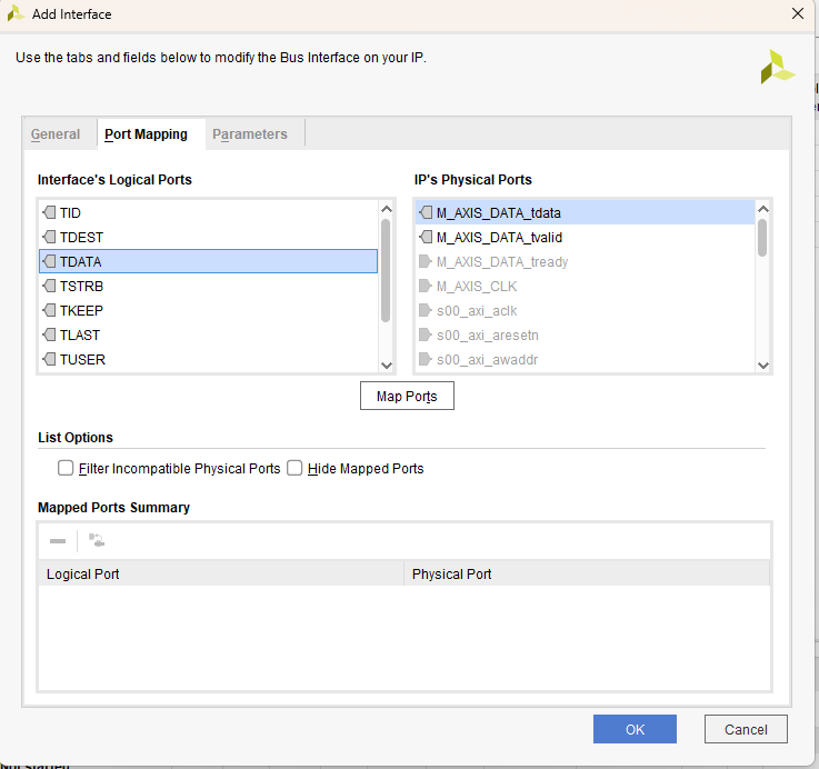
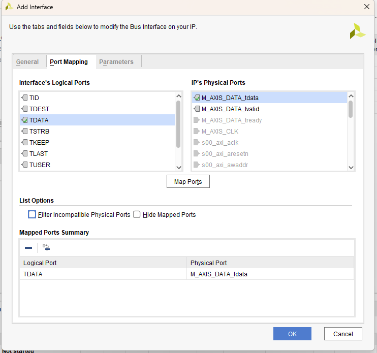
Click the Port Mapping tab. Match TDATA on the right (click it) with M_AXIS_DATA_tdata (click it) and then click Map Ports.
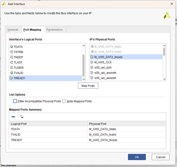
Repeat the same process for TVALID and M_AXIS_DATA_tvalid and TREADY and M_AXIS_DATA_tready. Click Ok.
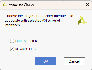
Right click the new peripheral created M_AXIS_DATA, and click Associate Clocks…
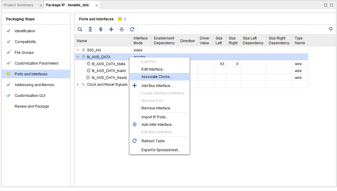
Check M_AXIS_CLK. Click Ok.
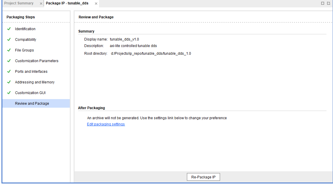
Click Review and Package. Click on Edit packaging settings.
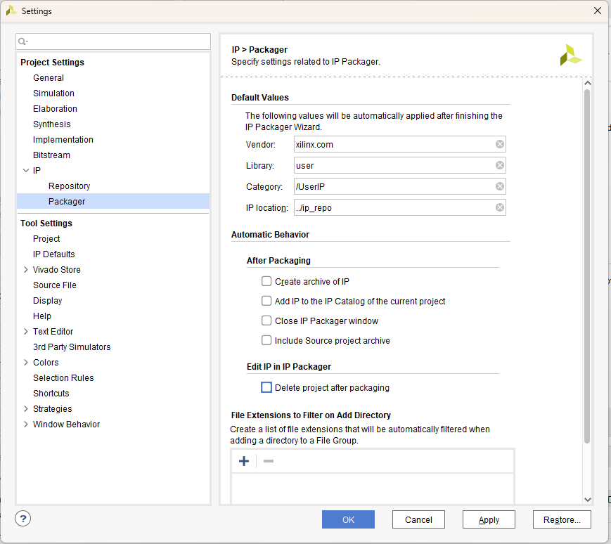
Ensure that Delete project after packaging is unchecked.
Note
CRITICALLY IMPORTANT: If Delete project after packaging is checked, this will delete your ability to further edit this IP and you will have to start all over. No clue why it is a default setting in Vivado that this is checked.
Once unchecked, click Ok.
Click Re-Package IP